Mechanical Interfaces
This section provides the maximum board dimensions, mounting points and the connector locations. The connector used is also documented.
Board dimensions, mounting points and connector location
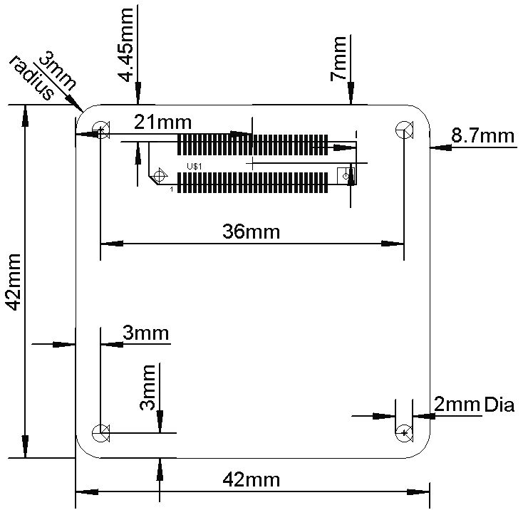
Figure 3.1 provides a technical drawing providing information on the maximum board dimensions, mounting points and connector locations. Please note that the board thickness is not provided. The board thickness is dependant on the design of the board. It should be noted that the thickness of the board will have an impact on the overall height of the board.
The dimensions of the board are stated as maximum as boards may require cut-outs.
 |
|---|
| Figure 3.1: Technical drawing of the board |
The connector on the top of the board is the HEADER version of the standard connector with the connector on the bottom of the board the RECEPTACLE version of the standard connector. This was done to allow the topside of the board to determine the height of the full design.
Connector Information
This section provides information regarding the connector series used. The connector series used is the Hirose FX8C. Details of the series are provided in Table 3.1. The range of heights available using this range are provided in Table 3.2.
| Table 3.1: Connector Details | |
|---|---|
| Series Name | Hirose FX8C |
| Part Number (excluding height) Header Part Number (excluding height) Receptacle | FX8C-60P-SV FX8C-60S-SV |
| Pitch | 0.6mm |
| Stacking Height (Connector) | 5 – 16 mm |
| Current Rating (Per Pin) | 0.4A (0.2A Derated) |
| Operating Temperature Range | -55°C to +85°C |
| Insulator Materials | PBS |
| Contact Material | Phosphor Bronze |
| Table 3.2: Connector Heights1 | ||
|---|---|---|
| Header | Receptacle | |
| FX8C-60S-SV | FX8C-60S-SV5 | |
| FX8C-60P-SV | 5mm | 10mm |
| FX8C-60P-SV1 | 6mm | 11mm |
| FX8C-60P-SV2 | 7mm | 12mm |
| FX8C-60P-SV4 | 9mm | 14mm |
| FX8C-60P-SV6 | 10mm | 16mm |
-
Note that the height is measured between the surface of each board. ↩